WebMail
  LiveChat
Top Questions On Breakthroughs with Figure 4
ANSWERS BY PATRICK DUNNE
The questions featured in this blog come from the audience of our live webinar on Breakthroughs with Figure 4 in Additive Manufacturing with Direct Digital Production. Hosted by VP, advanced applications engineer Patrick Dunne, and director of operations for 3D Systems On Demand, Tracy Beard, the webinar provided a step-by-step walkthrough of Figure 4’s performance in relatively high-volume requests, as well as a one to one comparison in time, labor, cost, and part quality of Figure 4 versus more traditional part production.
If you couldn’t join this presentation during the live session, it’s worth taking the time to listen to the recording. It includes a wealth of information about the Figure 4 printing process, our production-grade materials, the competitiveness of the Figure 4 methodology, and what applications this technology is set to alter.
And now on to your questions!
Technology
What are the differences in build process and post-process between Figure 4 and Stereolithography (SLA)?
The fundamental difference in build process between Figure 4 and SLA is that Figure 4 is a projection-based technology, whereas SLA is a laser vector-based technology. Because Figure 4 is projection-based, there is no time relationship between layer time and cross-sectional detail. As a vector-based process, SLA uses a single point of light to cure material that travels around the system at high speed. This means that for SLA there is a time correlation between cross-sectional area, as well as perimeter, detail, quantity, and complexity.
Because Figure 4 is projection-based, there is no time relationship between layer time and cross-sectional detail.
Another difference is in frequencies: typically, SLA is a 365nm, whereas Figure 4 is 405nm
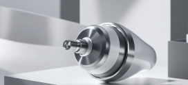
Lastly, with the Figure 4 build process, parts are built upside down, and the three-dimensional object is pulled upward from a membrane. With SLA, parts are built upright, submerged in a vat of fluid. Because Figure 4 parts are built on a non-contact membrane, there is no surface meniscus like you see with vat-based SLA, as such it is possible to achieve very thin layers. Combined with the projection process, print speeds with Figure 4 are also very high. In the example shown in the webinar, the vertical build speed was ~63mm/hr with a total build time of 5 hours and 15 minutes.
There is no appreciable difference between the post-processing of each technology.
What is the layer height on Figure 4?
The standard mode layer thickness of Figure 4 printing with Figure 4 PRO-BLK 10 production material is 0.05 mm. However this can be adjusted based on application requirements. We have examples of applications that go all the way down to 10um layer thickness.
What about dimensional stability between the first and the last layer of parts considering total weight (over 6kg) of all stacked parts pulling and stretching everything down?
Very consistent. There is very little variation as a function of when and where it was built within the system.
What’s the maximum build envelope on Figure 4?
The printable build volume (W x D x H) on Figure 4 Production and Figure 4 Modular systems is 124.8 x 70.2 x 346 mm (4.9 x 2.8 x 13.6 in). The printable build volume on the Figure 4 Standalone is 124.8 x 70.2 x 196 mm (4.9 x 2.8 x 7.7 in).
Is Figure 4 an isotropic process?
It is very close to isotropic. The mode of failure is non-planar material yielding fracture, and not layer delamination as a function of additive.
What is the total cost of the system including printer, wash system and curing system? Is there any other add on that is required to create parts (plus cost)?
We are happy to provide a price quote based on the entire scope of your production needs. To receive a quote, please request one through our contact page. Within the form, please select “Figure 4” and add comments about your project needs. A 3D Systems Specialist will reach out to complete your request. https://www.3dsystems.com/contact
Materials
Is Figure 4 PRO-BLK 10 similar to ABS, or stronger?
Figure 4 PRO-BLK 10 and ABS share some similar characteristics. A good place to start for a comparison, and to determine if Figure 4 PRO-BLK 10 will suit your needs, is with the Figure 4 PRO-BLK 10 datasheet.
Do you think 3D printing is going to overtake plastic injection? Not just in terms of time and price, but in the materials you can use and precision of the parts?
At this point, we don’t see additive manufacturing with the given technologies as completely replacing injection molding. We see AM taking its place in the manufacturer’s toolbox alongside injection molding, to augment injection molding in applicable cases with opportunities for small plastic part production.
In particular, we see 3D printing as offering a great advantage in low volume and/or higher value applications where the designer or engineer is adding design features, complexity, or textures.
How were these materials tested?
We have run our materials through accelerated environmental testing to simulate durability and wear over an extrapolated 5-year timeline. Testing includes cycles of UV, water, and heat and cold desiccation to replicate both indoor and outdoor long-term stability, and we are able to extrapolate the 5-year performance by running 400 hours of testing. In this testing, our Figure 4 PRO-BLK 10 demonstrates very good life cycle stability that is similar to off-the-shelf, commodity-grade polyurethane. When you look at the leading competitor in this space, Figure 4 PRO-BLK 10 is significantly better.
What about dual material printing (mixed plastic and metal parts)?
Assembly is required to achieve a combination metal and plastic part with Figure 4. If you have an application where this is required, please contact us and we can discuss your requirements
Is Figure 4 PRO-BLK 10 material available from 3D Systems On Demand manufacturing services?
We are currently installing a fleet of Figure 4 printers in our On Demand facilities to make Figure 4 widely available through our On Demand services. We anticipate being able to offer those services in the first half of 2020.
What kinds of production materials may become available for Figure 4?
One of the primary benefits of the Figure 4 platform relative to stereolithography is that you don’t need big batches of material, which makes it possible to experiment with more reactive chemistries at lower batch production volumes, to achieve novel properties and capabilities. This ultimately leads to novel applications. As a company we are continuing to innovate and develop new materials to expand the range of addressable applications.
What is the upper temperature rating on the cured material?
The upper heat deflection temperature of Figure 4 PRO-BLK 10 material is 70˚C. We also offer Figure 4 HI TEMP AMB-300, which has an upper heat deflection temperature of > 300˚C.

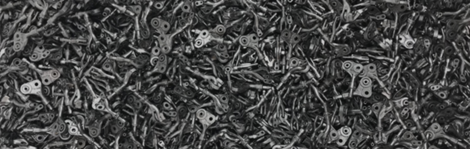
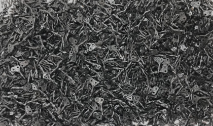
Stacked manufacturing enabled us to build 120 plastic components in a single build at an average speed of ~63 mm/hr.
Accuracy
What is the minimum wall thickness you can print with Figure 4 PRO-BLK 10 material?
It depends on aspect ratio, the orientation of features, and the material. With some electronic connector applications we have expressed 150um vertical walls for short length; we have also worked on production-scale mass complex casting applications that routinely express 300um vertical walls over several inches.
It is difficult to provide a general, catchall answer, because there are always aspect ratios to consider. For example, if you had a paper-thin, 100-micron sheet on a small area (say 5 by 5 millimeters), you could express that as a vertical 100-micron sheet and it would survive the washing process. Yet if you were to print a bigger sheet (for example, 50 by 50 millimeters), that would be too flexible and likely get washed away in post processing.
Detail fidelity with the Figure 4 platform is right up there, and in some cases beyond what you can express with injection molding, but geometry is important. Because of this, often the best advice is that before you scale up production, take the time to build a single copy of the part and determine whether the feature you have planned is viable.
How well does Figure 4 print hollow shells such as bottles?
Very well. Our advice is to look for opportunities for self-supporting orientations with bottles. In some cases you can span close to an inch with no supports on constrained bridges.
What is the part accuracy and tolerances Figure 4 can hold?
Accuracy is dependent on the geometry in question; not just the size of the part, but also the shape and cross-sections. As such, accuracy capability is best evaluated in the context of a specific part example. For the small plastic part in the presentation, we were able to get around 35 microns on average, with a range of +/- 150 microns. In a dental application for a 60,000 micron arch, we were able to keep 100% of surfaces within +/- 100 microns.
Applications
Is there a possibility of printing “dental resins” including denture base resins and teeth and if so how quickly?
3D Systems offers an extensive portfolio of dental materials under our NextDent brand. In fact, much of our learning around UV and lifecycle stabilization comes from the dental industry. You can learn more about our dental materials and the NextDent 5100 3D printer based on Figure 4 technology on the dental section of our website.
Design
What are some specific design considerations when designing parts for Figure 4?
The design considerations recommended for Figure 4 are similar to those recommended for any photopolymer 3D printing technology. A few of these considerations include things like orientation of the build, support structures, and how you will clean the part once printed.
From an orientation and support perspective, it’s good to think about integrating self-supporting structures and features into design. In terms of considerations for cleaning and post-curing, it is largely a matter of using common sense while thinking through the results of your build. For example, if you were to design a hollow sphere the size of ping pong ball with one pinpoint hole in it, that geometry would be filled with resin at the end of the print, and removing that resin through that opening would be tedious and difficult. You can do it, but remember a small design change up front can save a lot of downstream time at scale.
You will also want to give thought to the kinds of design considerations and fundamental ranges of capability that apply for any manufacturing device, such as minimal wall thicknesses and things of that nature, which tend to vary from geometry to geometry and part to part. Often the best way to determine the functional range for a specific application is to print it and test it. Iterate out all the opportunities for manufacturing efficiencies before you scale up to high volume production.
Some of the charts compared injection molding to Figure 4, but what about designing parts for AM that could never be injection molded?
Broadening design capability to increase part performance and manufacturing efficiency are major benefits of the additive manufacturing process. Some examples of this include reducing or eliminating assembly via monolithic part design, lowering part weight through design optimization, etc. These capabilities are major drivers of AM and increase the value of the technology beyond speed and quality to impact application function. For the purpose of the comparison within the webinar, we compared like parts with like parts to preserve the integrity of the findings.
Is there any consideration being given to adding inserts during the printing process: for example screw inserts?
It is not possible with commercially available product to add inserts during the printing process, but you could add them subsequently in post-processing. If you have an application where this is required, please contact us and we can discuss your requirements. From a technology perspective it is feasible, and we have done this in the past with other AM systems.
Is the 3D component optimized for printing or it is 3D made for traditional manufacturing?
In this case the part was designed for end functionality, with some optimization for the AM process itself. As such, this specific design is incompatible with formative technologies (IM), however it’s still very close to a traditional design.
Software
Is part stacking/nesting done manually, or do you have a 3D nesting software?
For the demonstration discussed within the webinar, we created a 3D array in CAD and generated 3D Sprint supports as if it was just a single STL file. To do that, you would do the array, save it as a single multi-shell STL file, and then treat it as a single part. There is room for optimization and integration into 3D Sprint in the future, but at this point it is a multi-step process.
Can you provide a link/video for minimizing the support structures?
Customers can always take advantage of the Help link in 3D Sprint to get assistance and clarification on process and best practices. Additionally, here is a video on intermediate tools within the software.
Post-Processing
How did you post-process these parts?
The cleaning process for these parts took a total of approximately 15 minutes of manual labor, as well as 90 minutes of hands-free part curing. The process was 20 dunk cycles in clean isopropyl alcohol (IPA), followed by an air-line dry, a second 20 cycles in a second clean IPA followed by a second air-line, and then curing in the Post-Curing Apparatus (lightbox).
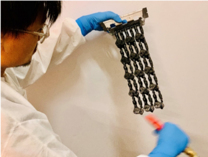
Figure 4 allows a batch of parts to be treated as a single part when it comes to post-processing.
How do nested parts work with post-curing? Can the post-cure UV light reach all surfaces of all the parts?
Vertical nesting imparts efficiencies of scale in post-processing as well as part building and allows the operator to treat a batch of parts the same as a single part. Therefore, if it takes 15 minutes to clean one part, that same 15 minutes is all that is required for the aggregated batch of 120 parts.
Source https://3dsystems.com/